
An ISTA 3A drop test packaging SOP is essential for protecting sensitive equipment from transit damage, yet many companies still experience broken cargo after passing their lab certifications. Research and development (R&D) and packaging engineers spend thousands of dollars sending custom crates and foam inserts to certified testing laboratories. The packaging successfully passes the controlled simulation, receives an official certification report, and gets approved for mass production. However, once full-scale global distribution begins, field reports tell a completely different story: internal circuit boards crack, optical assemblies misalign, and expensive equipment arrives Dead on Arrival (DOA).
Passing a laboratory simulation is only the first step in product development. A static laboratory report validates your initial packaging design, but it does not control real-world shipping conditions. To eliminate persistent shipping losses, enterprises must expand their design qualification into a daily packaging drop test validation standard that actively monitors handling across the entire logistics chain.
The Laboratory Illusion: The ASTM D4169 Transit Simulation Gap
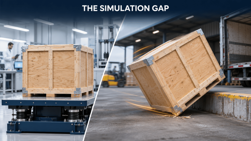
The reason certified packaging fails in the real world is simple: laboratories use controlled variables, while global logistics is entirely random. This disconnect is known in the packaging industry as the ASTM D4169 transit simulation gap.
In a certified testing facility, technicians use precision drop testers, pneumatic tables, and controlled hydraulic vibration platforms. The test box is dropped perfectly flat from a predetermined height onto a smooth, rigid steel or concrete plate. The kinetic shockwave travels symmetrically through the cushioning foam, allowing the internal cushioning to perform at maximum efficiency.
Real-world transport rarely behaves like a testing laboratory:
-
Asymmetrical and Angled Drops: In actual cargo hubs, packages are rarely dropped flat. Forklift operators drop crates on their corners or edges, concentrating all impact energy into a single structural point where internal foam can crack or bottom out.
-
Complex Multi-Axis Jolts: During international transport, freight experiences simultaneous vertical drops, lateral acceleration, and continuous road vibration. Laboratory tests typically apply these forces sequentially, missing the cumulative destruction of simultaneous multi-axis stress.
-
Uncontrolled Handling Heights: A standard test might evaluate drops from 30 to 48 inches based on cargo weight. However, on busy loading docks, crates can fall from elevated truck beds or be thrown from cargo containers at heights far exceeding certified test thresholds.
Because of this ASTM D4169 transit simulation gap, relying solely on a pre-production test report leaves your mass production shipments completely unprotected against aggressive manual handling.
Quantifying Fragility: Product Fragility G-Factor Calculation in Production
To solve this problem, engineers must take the theoretical numbers from their engineering files and apply them to daily factory operations. Every sensitive product has a critical shock tolerance level, established during packaging design through a product fragility G-factor calculation.
The G-factor represents the maximum acceleration force an item can absorb before mechanical or electrical failure occurs. For example, heavy industrial castings might endure 75G to 100G, while precision medical electronics, semiconductor wafer handlers, or enterprise servers can fail at forces as low as 25G or 37G.
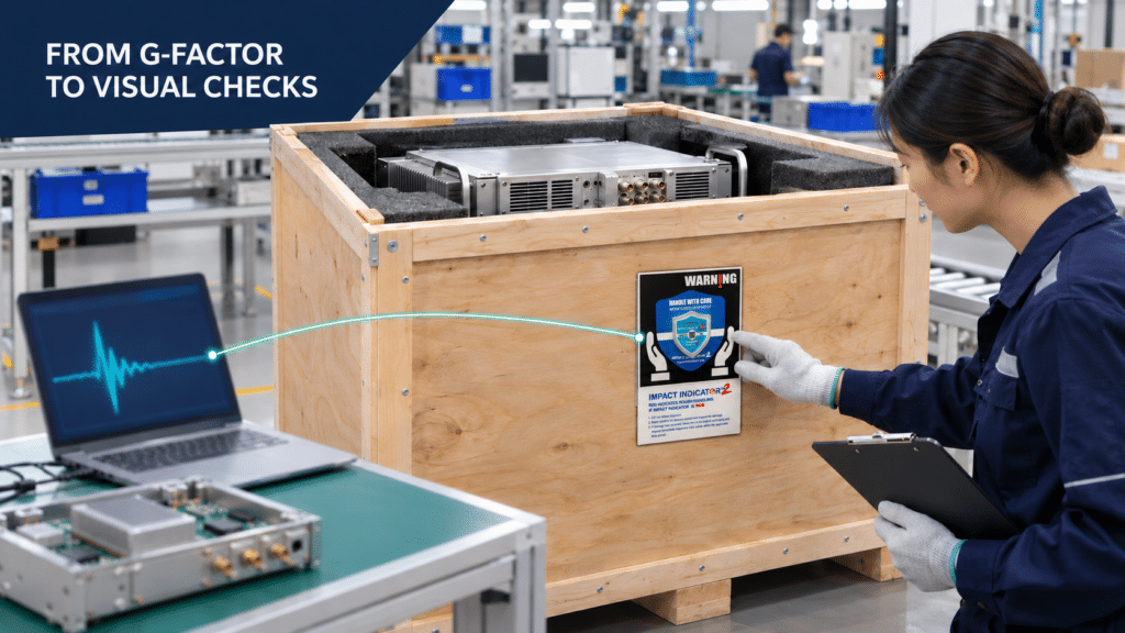
Unfortunately, this product fragility G-factor calculation often stays buried in R&D engineering archives. Factory packing staff and warehouse receiving docks have no way to visually measure the G-force experienced by a shipping box during daily operations. They cannot attach expensive laboratory accelerometers to thousands of outgoing wooden crates.
The solution is translating the engineering G-factor into a clear Go No-Go packaging inspection protocol. By mounting calibrated physical indicators directly to the outside of the packaging, warehouse personnel can immediately see whether a shipment remained within its safe acceleration limits without needing technical instruments.
Deploying a Mechanical Shock Indicator for Drop Testing and Mass Production
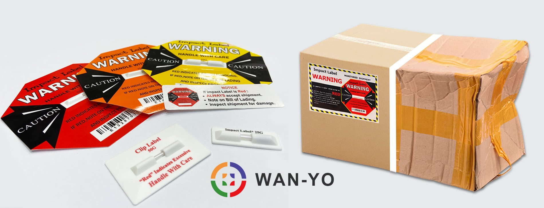
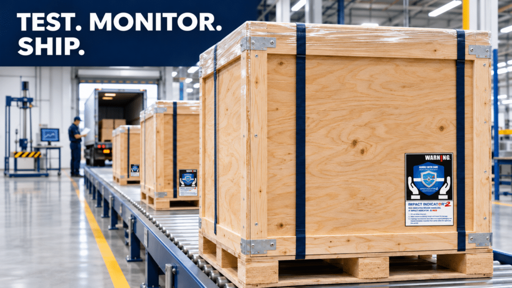
To enforce a reliable inspection threshold, companies must deploy a durable mechanical shock indicator for drop testing that transitions seamlessly from lab trials to high-volume shipping. The Impact Indicator 2 provides this exact operational capability.
The Impact Indicator 2 is an internationally recognized, precision-engineered impact sensor. It operates using calibrated physical mechanics rather than delicate electrical circuits or chemical liquids. When an impact exceeds the specified G-force rating (such as 25G, 37G, 50G, 75G, or 100G), a mechanical trigger activates an irreversible visual change, turning the display window bright red.
Integrating the Impact Indicator 2 into your ISTA 3A drop test packaging SOP delivers distinct operational advantages:
-
Zero False Alarms: Traditional legacy impact labels frequently trigger during normal truck transport or mild forklift vibrations, creating false alarms. The Impact Indicator 2 is mechanically tuned to respond only to acute, damaging impacts, ensuring that normal logistics handling does not trigger a false reading.
-
Zero Battery and Aviation Restrictions: Because it is 100% mechanical and contains no lithium batteries, it complies with all international air cargo safety regulations without requiring hazardous goods declarations.
-
Immediate Visual Deterrence: The high-visibility warning label alerts handlers that the cargo is actively monitored. When dock workers see the indicator, they handle the package with significantly more care, preventing mishandling before it happens.
Micro-Tilt Defense: The 20 Degree Tilt Indicator for Precision Equipment
Vertical drops are not the only threat to sensitive equipment. Heavy machinery, liquid-cooled servers, laboratory centrifuges, and industrial gearboxes often have high centers of gravity. These shipments are highly vulnerable to tipping, rolling, and acute inclination during forklift transport or abrupt vehicle cornering.
Standard tilt indicators on the market do not provide sufficient protection for high-value assets because they typically trigger only after the box reaches a 30-degree, 45-degree, or 80-degree angle. For precision instrumentation, allowing a 25-degree lean can cause lubricating oil to flood sensitive pneumatic tubes, dislodge internal optical lenses, or misalign mechanical gear assemblies.
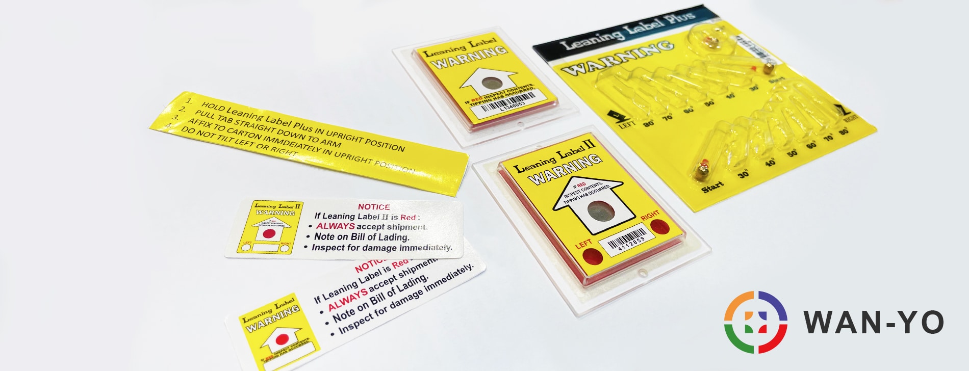
To address this vulnerability, packaging engineers must implement a 20 degree tilt indicator for precision equipment. The Leaning Label Plus 20/80 is specifically designed for ultra-sensitive cargo:
-
Breakthrough 20° Minimum Detection: Unlike standard indicators, the Leaning Label Plus 20/80 provides early-stage detection starting at an industry-leading 20 degrees, catching micro-tilts before catastrophic structural failure occurs.
-
Complete Multi-Angle Tracking: It records tilt angles across 20°, 30°, 40°, 50°, 60°, 70°, and 80° in both left and right directions, alongside a 180° complete overturn indicator.
-
Patented Anti-Backtrack Groove: Once the internal brass indicator balls fall into an angle pocket, a patented channel prevents them from rolling back. Even if a handler quickly straightens the tilted crate, the physical evidence remains permanently locked in place.

The 4-Step Packaging Drop Test Validation Standard SOP
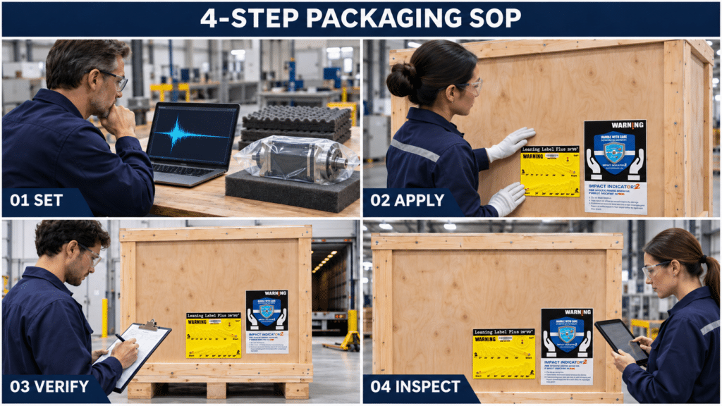
To bridge the gap between design validation and daily outbound shipping, packaging and quality teams can implement this practical 4-step SOP:
Step 1: Baseline Threshold Mapping
Use your laboratory drop test data and internal product fragility G-factor calculation to select your physical thresholds. If your product shows internal circuit failure at 30G during drop testing, specify a 25G Impact Indicator 2. If mechanical balance is compromised at a slight angle, assign the Leaning Label Plus 20/80 with a 20-degree warning limit.
Step 2: Symmetrical and Dual-Axis Placement
Apply indicators strategically to cover every axis of motion:
-
Mount the Impact Indicator 2 on the lower corner of the longest crate face, close to the structural base where impact shocks travel directly into the frame.
-
Mount the Leaning Label Plus 20/80 on the upper section of the crate near the package’s center of gravity to detect early rotational movement.
Step 3: Outbound Quality Check and Bill of Lading (BOL) Notification
Before releasing goods from the manufacturing plant, packing personnel inspect both indicators to verify they are in their unactivated states. Attach a companion warning label and a dedicated alert sticker to the Bill of Lading (BOL). This officially notifies freight carriers that specific handling parameters are being enforced.
Step 4: Enforce the Go No-Go Packaging Inspection Protocol at Receiving
Establish an unboxing inspection protocol with your receiving warehouses, 3PL partners, and end clients:
-
Green / Clear (Go): If both indicators remain clear, the cargo has stayed within certified testing limits. The receiving dock signs the clean delivery receipt and releases the equipment for immediate deployment.
-
Red / Activated (No-Go): If the Impact Indicator 2 has turned red or the Leaning Label Plus 20/80 shows an inclination beyond 20 degrees, the receiver must note the exception directly on the delivery receipt before signing. The package is moved to a diagnostic staging area for internal inspection before acceptance.
Implement a Reliable Packaging Drop Test Validation Standard Today
Do not allow high testing expenses to be wasted on uncontrolled shipping lanes. Protect your product design from assembly to delivery by establishing clear, enforceable handling standards on every crate.
Provide your packaging dimensions, total gross shipment weight, product fragility limits, and current transit routes to our engineering team. We will review your technical parameters and provide the exact sensitivity configurations required for your operations.